MRI is a relatively new technology, which has been in use for little more than 30 years (compared with over 110 years for X-ray radiography). The first MRI Image was published in 1973 and the first study performed on a human took place on July 3, 1977.
Magnetic resonance imaging was developed from knowledge gained in the study of nuclear magnetic resonance. In its early years the technique was referred to as nuclear magnetic resonance imaging (NMRI). However, as the word nuclear was associated in the public mind with ionizing radiation exposure it is generally now referred to simply as MRI. Scientists still use the term NMRI when discussing non-medical devices operating on the same principles. The term Magnetic Resonance Tomography (MRT) is also sometimes used. One of the contributors to modern MRI, Paul Lauterbur, originally named the technique zeugmatography, a Greek term meaning "that which is used for joining". The term referred to the interaction between the static, radiofrequency, and gradient magnetic fields necessary to create an image, but this term was not adopted.

Sagittal MR image of the knee

with aliasing artifacts (nose and forehead in the back of the head)
How MRI works
Brief lay explanation of MRI physics
The body is mainly composed of water molecules which each contain two hydrogen nuclei or protons. When a person goes inside the powerful magnetic field of the scanner these protons align with the direction of the field.
A second radiofrequency electromagnetic field is then briefly turned on causing the protons to absorb some of its energy. When this field is turned off the protons release this energy at a radiofrequency which can be detected by the scanner. The position of protons in the body can be determined by applying additional magnetic fields during the scan which allows an image of the body to be built up. These are created by turning gradients coils on and off which creates the knocking sounds heard during an MR scan.
Diseased tissue, such as tumors, can be detected because the protons in different tissues return to their equilibrium state at different rates. By changing the parameters on the scanner this effect is used to create contrast between different types of body tissue.
Contrast agents may be injected intravenously to enhance the appearance of blood vessels, tumors or inflammation. Contrast agents may also be directly injected into a joint, in the case of arthrograms, MR images of joints. Unlike CT scanning MRI uses no ionizing radiation and is generally a very safe procedure. Patients with some metal implants, cochlear implants, and cardiac pacemakers are prevented from having an MRI scan due to effects of the strong magnetic field and powerful radiofrequency pulses.
MRI is used to image every part of the body, and is particularly useful in neurological conditions, disorders of the muscles and joints, for evaluating tumors and showing abnormalities in the heart and blood vessels.
Physics principles
Nuclear magnetism

Subatomic particles such as protons have the quantum mechanical property of spin. Certain nuclei such as 1H (protons), 2H, 3He, 23Na or 31P, have a non–zero spin and therefore a magnetic moment. In the case of the so-called spin-1/2 nuclei, such as 1H, there are two spin states, sometimes referred to as "up" and "down". Nuclei such as 12C have no unpaired neutrons or protons, and no net spin: however the isotope 13C (referred to as "carbon 13") does.
When these spins are placed in a strong external magnetic field they precess around an axis along the direction of the field. Protons align in two energy eigenstates (Zeeman effect) one low-energy, and one high-energy, which are separated by a certain splitting energy.
Resonance and relaxation
In the static magnetic fields commonly used in MRI, the energy difference between the nuclear spin states corresponds to a photon at radio frequency (rf) wavelengths. Resonant absorption of energy by the protons due to an external oscillating magnetic field will occur at the Larmor frequency for the particular nucleus.
The net magnetization vector has two components. The longitudinal magnetization is due to a tiny excess of protons in the lower energy state. This gives a net polarization parallel to the external field. Application of an rf pulse can destroy (with a so-called 90° pulse) or even reverse (with a so-called 180° pulse) this polarization vector. The transverse magnetization is due to coherences forming between the two proton energy states following an rf pulse typically of 90°. This gives a net polarization perpendicular to the external field in the transverse plane. The recovery of longitudinal magnetization is called longitudinal or T1 relaxation and occurs exponentially with a time constant T1. The loss of phase coherence in the transverse plane is called transverse or T2 relaxation. T1 is thus associated with the enthalpy of the spin system (the amount of spins in parallel/anti-parallel state) while T2 is associated with its entropy (the amount of spins in phase).
When the radio frequency pulse is turned off, the transverse vector component produces an oscillating magnetic field which induces a small current in the receiver coil. This signal is called the free induction decay (FID). In an idealized nuclear magnetic resonance experiment, the FID decays approximately exponentially with a time constant T2, but in practical MRI small differences in the static magnetic field at different spatial locations ("inhomogeneities") cause the Larmor frequency to vary across the body creating destructive interference which shortens the FID. The time constant for the observed decay of the FID is called the T2* ("T 2 star") relaxation time, and is always shorter than T2. Also, when the radio frequency pulse is turned off, the longitudinal magnetization starts to recover exponentially with a time constant T1
In MRI, the static magnetic field is caused to vary across the body (a field gradient), so that different spatial locations become associated with different precession frequencies. Usually these field gradients are pulsed, and it is the almost infinite variety of rf and gradient pulse sequences that gives MRI its versatility. Application of field gradient destroys the FID signal, but this can be recovered and measured by a refocusing gradient (to create a so-called "gradient echo"), or by a radio frequency pulse (to create a so-called "spin-echo"). The whole process can be repeated when some T1-relaxation has occurred and the thermal equilibrium of the spins has been more or less restored.
Typically in soft tissues T1 is around one second while T2 and T2* are a few tens of milliseconds, but these values vary widely between different tissues (and different external magnetic fields), giving MRI its tremendous soft tissue contrast.
Contrast agents work by altering (shortening) the relaxation parameters, especially T1.
Imaging
A number of schemes have been devised for combining field gradients and radiofrequency excitation to create an image. One involves 2D or 3D reconstruction from projections, much as in Computed Tomography. Others involve building the image point-by-point or line-by-line. One even uses gradients in the rf field rather than the static field. Although each of these schemes is occasionally used in specialist applications, the majority of MR Images today are created either by the Two-Dimensional Fourier Transform (2DFT) technique with slice selection, or by the Three-Dimensional Fourier Transform (3DFT) technique. Another name for 2DFT is spin-warp. What follows here is a description of the 2DFT technique with slice selection.
Slice selection is achieved by applying a magnetic gradient in addition to the external magnetic field during the radio frequency pulse. Only one plane within the object will have protons that are on–resonance and contribute to the signal.
A real image can be considered as being composed of a number of spatial frequencies at different orientations. A two–dimensional Fourier transformation of a real image will express these waves as a matrix of spatial frequencies known as k–space. Low spatial frequencies are represented at the center of k–space and high spatial frequencies at the periphery. Frequency and phase encoding are used to measure the amplitudes of a range of spatial frequencies within the object being imaged.
The frequency encoding gradient is applied during readout of the signal and is orthogonal to the slice selection gradient. During application of the gradient the frequency differences in the readout direction progressively change. At the midpoint of the readout these differences are small and the low spatial frequencies in the image are sampled filling the center of k-space. Higher spatial frequencies will be sampled towards the beginning and end of the readout filling the periphery of k-space.
Phase encoding is applied in the remaining orthogonal plane and uses the same principle of sampling the object for different spatial frequencies. However, it is applied for a brief period before the readout and the strength of the gradient is changed incrementally between each radio frequency pulse. For each phase encoding step a line of k–space is filled.
Either a spin echo or a gradient echo can be used to refocus the magnetisation.
The 3DFT technique is rather similar except that there is no slice selection and phase-encoding is performed two separate directions.
Another scheme which is sometimes used, especially in brain scanning or where images are needed very rapidly, is called echo-planar imaging (EPI): in this case each rf excitation is followed by a whole train of gradient echoes with different spatial encoding.
Image contrast and contrast enhancement
Image contrast is created by differences in the strength of the NMR signal recovered from different locations within the sample. This depends upon the relative density of excited nuclei (usually water protons), on differences in relaxation times (T1, T2 and T2 * ) of those nuclei after the pulse sequence, and often on other parameters discussed under specialized MR scans. Contrast in most MR images is actually a mixture of all these effects, but careful design of the imaging pulse sequence allows one contrast mechanism to be emphasized while the others are minimized. The ability to choose different contrast mechanisms gives MRI tremendous flexibility. In the brain, T1-weighting causes the nerve connections of white matter to appear white, and the congregations of neurons of gray matter to appear gray, while cerebrospinal fluid (CSF) appears dark. The contrast of white matter, gray matter and cerebrospinal fluid is reversed using T2 or T2 * imaging, whereas proton-density-weighted imaging provides little contrast in healthy subjects. Additionally, functional parameters such as cerebral blood flow (CBF), cerebral blood volume (CBV) or blood oxygenation can affect T1, T2 and T2 * and so can be encoded with suitable pulse sequences.
In some situations it is not possible to generate enough image contrast to adequately show the anatomy or pathology of interest by adjusting the imaging parameters alone, in which case a contrast agent may be administered. This can be as simple as water, taken orally, for imaging the stomach and small bowel. However, most contrast agents used in MRI are selected for their specific magnetic properties. Most commonly, a paramagnetic contrast agent (usually a gadolinium compound) is given. Gadolinium-enhanced tissues and fluids appear extremely bright on T1-weighted images. This provides high sensitivity for detection of vascular tissues (e.g. tumors) and permits assessment of brain perfusion (e.g. in stroke). There have been concerns raised recently regarding the toxicity of gadolinium-based contrast agents and their impact on persons with impaired kidney function. The American College of Radiology released screening criteria for patients intended to be given Gadolinium-based contrast agents to identify potential risk factors for negative reactions. Special actions may be taken, such as hemodialysis following a contrast MRI scan for renally-impaired patients.
More recently, superparamagnetic contrast agents (e.g. iron oxide nanoparticles) have become available. These agents appear very dark on T2*-weighted images and may be used for liver imaging, as normal liver tissue retains the agent, but abnormal areas (e.g. scars, tumors) do not. They can also be taken orally, to improve visualization of the gastrointestinal tract, and to prevent water in the gastrointestinal tract from obscuring other organs (e.g. pancreas). Diamagnetic agents such as barium sulfate have also been studied for potential use in the gastrointestinal tract, but are less frequently used.
K-space
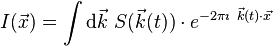
In 1983 Ljunggren and Tweig independently introduced the k-space formalism, a technique that proved invaluable in unifying different MR imaging techniques. They showed that the demodulated MR signal S(t) generated by freely precessing nuclear spins in the presence of a linear magnetic field gradient G equals the Fourier transform of the effective spin density i.e.

where:
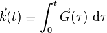
In other words, as time progresses the signal traces out a trajectory in k-space with the velocity vector of the trajectory proportional to the vector of the applied magnetic field gradient. By the term effective spin density we mean the true spin density  corrected for the effects of T1 preparation, T2 decay, dephasing due to field inhomogeneity, flow, diffusion, etc. and any other phenomena that affect that amount of transverse magnetization available to induce signal in the RF probe.
From the basic k-space formula, it follows immediately that we reconstruct an image  simply by taking the inverse Fourier transform of the sampled data viz.
Using the k-space formalism, a number of seemingly complex ideas became simple. For example, it becomes very easy to understand the role of phase encoding (the so-called spin-warp method). In a standard spin echo or gradient echo scan, where the readout (or view) gradient is constant (e.g. Gx), a single line of k-space is scanned per RF excitation. When the phase encoding gradient is zero, the line scanned is the kx axis. When a non-zero phase-encoding pulse is added in between the RF excitation and the commencement of the readout gradient, this line moves up or down in k-space i.e. we scan the line ky=constant.
The k-space formalism also makes it very easy to compare different scanning techniques. In single-shot EPI, all of k-space is scanned in a single shot, following either a sinusoidal or zig-zag trajectory. Since alternating lines of k-space are scanned in opposite directions, this must be taken into account in the reconstruction. Multi-shot EPI and fast spin echo techniques acquire only part of k-space per excitation. In each shot, a different interleaved segment is acquired, and the shots are repeated until k-space is sufficiently well-covered. Since the data at the center of k-space represent lower spatial frequencies than the data at the edges of k-space, the TE value for the center of k-space determines the image's T2 contrast.
The importance of the center of k-space in determining image contrast can be exploited in more advanced imaging techniques. One such technique is spiral acquisition - a rotating magnetic field gradient is applied, causing the trajectory in k-space to trace out spiral out from the center to the edge. Due to T2 and T2 * decay the signal is greatest at the start of the acquisition, hence acquiring the center of k-space first improves contrast to noise ratio (CNR) when compared to conventional zig-zag acquisitions, especially in the presence of rapid movement.
Since  and
and  are conjugate variables (with respect to the Fourier transform) we can use the Nyquist theorem to show that the step in k-space determines the field of view of the image (maximum frequency that is correctly sampled) and the maximum value of k sampled determines the resolution i.e..

(these relationships apply to each axis [X, Y, and Z] independently).
Example of a pulse sequence

In the timing diagram, the horizontal axis represents time. The vertical axis represents: (top row) amplitude of radiofrequency pulses; (middle rows) amplitudes of the three orthogonal magnetic field gradient pulses; and (bottom row) receiver analog-to-digital converter (ADC). Radiofrequencies are transmitted at the Larmor frequency of the nuclide to be imaged: for example for 1H in a magnetic field of 1T, a frequency of 42.5781 MHz would be employed. The three field gradients are labeled GX (typically corresponding to a patient's Left-to-Right direction and colored red in diagram), GY (typically corresponding to a patient's Front-to-Back direction and colored green in diagram), and GZ (typically corresponding to a patient's Head-to-Toe direction and colored blue in diagram). Where negative-going gradient pulses are shown, they represent reversal of the gradient direction, i.e. Right-to-Left, Back-to-Front or Toe-to-Head. For human scanning gradient strengths of 1-100 mT/m are employed: higher gradient strengths permit better resolution and faster imaging. The pulse sequence shown here would produce a transverse (axial) image.
The first part of the pulse sequence, SS, achieves Slice Selection. A shaped pulse (shown here with a sinc modulation) causes a 90° (π/2 radian) nutation of longitudinal nuclear magnetization within a slab, or slice, creating transverse magnetization. The second part of the pulse sequence, PE, imparts a phase shift upon the slice-selected nuclear magnetization, varying with its location in the Y direction. The third part of the pulse sequence, another Slice Selection (of the same slice) uses another shaped pulse to cause a 180° (π radian) rotation of transverse nuclear magnetization within the slice. This transverse magnetisation refocuses to form a spin echo at a time TE. During the spin echo, a frequency-encoding (FE) or readout gradient is applied, making the resonant frequency of the nuclear magnetization vary with its location in the X direction. The signal is sampled nFE times by the ADC during this period, as represented by the vertical lines. Typically nFE of between 128 and 512 samples are taken.
The longitudinal relaxation is then allowed to recover somewhat and after a time TR the whole sequence is repeated nPE times, but with the phase-encoding gradient incremented (indicated by the horizontal hatching in the green gradient block). Typically nPE of between 128 and 512 repetitions are made.
The negative-going lobes in GX and GZ are imposed to ensure that, at time TE (the spin echo maximum), phase only encodes spatial location in the Y direction.
Typically TE is between 5 ms and 100 ms, while TR is between 100 ms and 2000 ms.
After the two-dimensional matrix (typical dimension between 128x128 and 512x512) has been acquired, producing the so-called K-space data, a two-dimensional Fourier transform is performed to provide the familiar MR image. Either the magnitude or phase of the Fourier transform can be taken, the former being far more common.
Scanner construction and operation

The three systems described above form the major components of an MRI scanner: a static magnetic field, an RF transmitter and receiver, and three orthogonal, controllable magnetic gradients.
Magnet
The magnet is the largest and most expensive component of the scanner, and the remainder of the scanner is built around it. Just as important as the strength of the main magnet is its precision. The straightness of the magnetic lines within the center (or, as it is technically known, the iso-center) of the magnet needs to be near-perfect. This is known as homogeneity. Fluctuations (non-homogeneities in the field strength) within the scan region should be less than three parts per million (3 ppm). Three types of magnets have been used:
- Permanent magnet: Conventional magnets made from ferromagnetic materials (e.g., steel alloys containing rare earth elements such as neodymium) can be used to provide the static magnetic field. A permanent magnet that is powerful enough to be used in an MRI will be extremely large and bulky; they can weigh over 100 tonnes. Permanent magnet MRIs are very inexpensive to maintain; this cannot be said of the other types of MRI magnets; but there are significant drawbacks to using permanent magnets. They are only capable of achieving weak field strengths compared to other MRI magnets (usually less than 0.4 T), and they are of limited precision and stability. Permanent magnets also present special safety issues; since their magnetic fields cannot be "turned off," ferromagnetic objects are virtually impossible to remove from them once they come into direct contact. Permanent magnets also require special care when they are being brought to their site of installation.
- Resistive electromagnet: A solenoid wound from copper wire is an alternative to a permanent magnet. An advantage is low initial cost, but field strength and stability are limited. The electromagnet requires considerable electrical energy during operation which can make it expensive to operate. This design is essentially obsolete.
- Superconducting electromagnet: When a niobium-titanium or niobium-tin alloy is cooled by liquid helium to 4K (−269°C, −452°F) it becomes a superconductor, losing resistance to flow of electrical current. An electromagnet constructed with superconductors can have extremely high field strengths, with very high stability. The construction of such magnets is extremely costly, and the cryogenic helium is expensive and difficult to handle. However, despite its cost, helium cooled superconducting magnets are the most common type found in MRI scanners today.
Most superconducting magnets have their coils of superconductive wire immersed in liquid helium, inside a vessel called a cryostat. Despite thermal insulation, ambient heat causes the helium to slowly boil off. Such magnets, therefore, require regular topping-up with liquid helium. Generally a cryocooler, also known as a coldhead, is used to recondense some helium vapor back into the liquid helium bath. Several manufacturers now offer 'cryogenless' scanners, where instead of being immersed in liquid helium the magnet wire is cooled directly by a cryocooler.
Magnets are available in a variety of shapes. However, permanent magnets are most frequently 'C' shaped, and superconducting magnets most frequently cylindrical. However, C-shaped superconducting magnets and box-shaped permanent magnets have also been used.
Magnetic field strength is an important factor in determining image quality. Higher magnetic fields increase signal-to-noise ratio, permitting higher resolution or faster scanning. However, higher field strengths require more costly magnets with higher maintenance costs, and have increased safety concerns. 1.0 - 1.5T field strengths are a good compromise between cost and performance for general medical use. However, for certain specialist uses (e.g., brain imaging), field strengths up to 3.0 T may be desirable.
Radio frequency system
The radio frequency (RF) transmission system consists of a RF synthesizer, power amplifier and transmitting coil. This is usually built into the body of the scanner. The power of the transmitter is variable, but high-end scanners may have a peak output power of up to 35 kW, and be capable of sustaining average power of 1 kW. The receiver consists of the coil, pre-amplifier and signal processing system. While it is possible to scan using the integrated coil for transmitting and receiving, if a small region is being imaged then better image quality is obtained by using a close-fitting smaller coil. A variety of coils are available which fit around parts of the body, e.g., the head, knee, wrist, breast, or internally, e.g., the rectum.
A recent development in MRI technology has been the development of sophisticated multi-element phased array coils which are capable of acquiring multiple channels of data in parallel. This 'parallel imaging' technique uses unique acquisition schemes that allow for accelerated imaging, by replacing some of the spatial coding originating from the magnetic gradients with the spatial sensitivity of the different coil elements. However, the increased acceleration also reduces the signal-to-noise ratio and can create residual artifacts in the image reconstruction. Two frequently used parallel acquisition and reconstruction schemes are known as SENSE[9] and GRAPPA.[10] A detailed review of parallel imaging techniques can be found here:[11]
Gradients
Gradient coils are used to spatially encode the positions of protons by varying the magnetic field linearly across the imaging volume. The Larmor frequency will then vary as a function of position in the x, y and z-axes.
Gradient coils are usually resistive electromagnets powered by sophisticated amplifiers which permit rapid and precise adjustments to their field strength and direction. Typical gradient systems are capable of producing gradients from 20 mT/m to 100 mT/m (i.e. in a 1.5 T magnet, when a maximal z-axis gradient is applied the field strength may be 1.45 T at one end of a 1 m long bore, and 1.55 T at the other). It is the magnetic gradients that determine the plane of imaging - because the orthogonal gradients can be combined freely, any plane can be selected for imaging.
Scan speed is dependent on performance of the gradient system. Stronger gradients allow for faster imaging, or for higher resolution; similarly, gradients systems capable of faster switching can also permit faster scanning. However, gradient performance is limited by safety concerns over nerve stimulation.
Some important characteristic of gradient amplifiers and gradient coil are: slew rate and gradient strength. As mentioned earlier, a gradient coil will create an additional, linearly varying magnetic field that adds or subtracts from the main magnetic field. This additional magnetic field will be have components in all 3 directions, viz. X, Y and Z; however, only the component along the magnetic field (usually called the Z-axis, hence denoted Gz) is useful for imaging. Along any given axis, the gradient will add to the magnetic field on one side of the zero position and subtract from it on the other side. Since the additional field is a gradient, it has units of Gauss per cm or miliTesla (mT) per meter. High performance gradient coils used in MRI are typically capable of producing a gradient magnetic field of approximate 30 mT per meter or higher for a 1.5 T MRI. The slew rate of a gradient system is a measure of how quickly the gradients can be ramped on or off. Typical higher performance gradients have a slew rate of up to 100-200 Tesla per meter per second. The slew rate depends both on the gradient coil (it takes more time to ramp up or down a large coil than a small coil) and the performance of the gradient amplifier (it takes a lot of voltage to overcome the inductance of the coil)and has adequate influence on image quality.
Applications
In clinical practice, MRI is used to distinguish pathologic tissue (such as a brain tumor) from normal tissue. One advantage of an MRI scan is that it is harmless to the patient. It uses strong magnetic fields and non-ionizing radiation in the radio frequency range. Compare this to CT scans and traditional X-rays which involve doses of ionizing radiation and may increase the risk of malignancy, especially in a fetus.
While CT provides good spatial resolution (the ability to distinguish two structures an arbitrarily small distance from each other as separate), MRI provides comparable resolution with far better contrast resolution (the ability to distinguish the differences between two arbitrarily similar but not identical tissues). The basis of this ability is the complex library of pulse sequences that the modern medical MRI scanner includes, each of which is optimized to provide image contrast based on the chemical sensitivity of MRI.
For example, with particular values of the echo time (TE) and the repetition time (TR), which are basic parameters of image acquisition, a sequence will take on the property of T2-weighting. On a T2-weighted scan, water- and fluid-containing tissues are bright (most modern T2 sequences are actually fast T2 sequences) and fat-containing tissues are dark. The reverse is true for T1-weighted images. Damaged tissue tends to develop edema, which makes a T2-weighted sequence sensitive for pathology, and generally able to distinguish pathologic tissue from normal tissue. With the addition of an additional radio frequency pulse and additional manipulation of the magnetic gradients, a T2-weighted sequence can be converted to a FLAIR sequence, in which free water is now dark, but edematous tissues remain bright. This sequence in particular is currently the most sensitive way to evaluate the brain for demyelinating diseases, such as multiple sclerosis.
The typical MRI examination consists of 5-20 sequences, each of which are chosen to provide a particular type of information about the subject tissues. This information is then synthesized by the interpreting physician.
Specialized MRI scans
Diffusion MRI

Diffusion MRI measures the diffusion of water molecules in biological tissues. In an isotropic medium (inside a glass of water for example) water molecules naturally move randomly according to Brownian motion. In biological tissues however, the diffusion may be anisotropic. For example a molecule inside the axon of a neuron has a low probability of crossing the myelin membrane. Therefore the molecule will move principally along the axis of the neural fiber. If we know that molecules in a particular voxel diffuse principally in one direction we can make the assumption that the majority of the fibers in this area are going parallel to that direction.
The recent development of diffusion tensor imaging (DTI) enables diffusion to be measured in multiple directions and the fractional anisotropy in each direction to be calculated for each voxel. This enables researchers to make brain maps of fiber directions to examine the connectivity of different regions in the brain (using tractography) or to examine areas of neural degeneration and demyelination in diseases like Multiple Sclerosis.
Another application of diffusion MRI is diffusion-weighted imaging (DWI). Following an ischemic stroke, DWI is highly sensitive to the changes occurring in the lesion. It is speculated that increases in restriction (barriers) to water diffusion, as a result of cytotoxic edema (cellular swelling), is responsible for the increase in signal on a DWI scan. The DWI enhancement appears within 5-10 minutes of the onset of stroke symptoms (as compared with computed tomography, which often does not detect changes of acute infarct for up to 4–6 hours) and remains for up to two weeks. Coupled with imaging of cerebral perfusion, researchers can highlight regions of "perfusion/diffusion mismatch" that may indicate regions capable of salvage by reperfusion therapy.
Like many other specialized applications, this technique is usually coupled with a fast image acquisition sequence, such as echo planar imaging sequence.
Magnetization Transfer MRI
Magnetization transfer (MT) refers to the transfer of longitudinal magnetization from free water protons to hydration water protons in NMR and MRI.
In magnetic resonance imaging of molecular solutions, such as protein solutions, two types of water molecules, free (bulk) and hydration, are found. Free water protons have faster average rotational frequency and hence less fixed water molecules that may cause local field inhomogeneity. Because of this uniformity, most free water protons have resonance frequency lying narrowly around the normal proton resonance frequency of 63 MHz (at 1.5 tesla). This also results in slower transverse magnetization dephasing and hence longer T2. Conversely, hydration water molecules are slowed down by interaction with solute molecules and hence create field inhomogeneities that lead to wider resonance frequency spectrum.
[edit] Fluid attenuated inversion recovery (FLAIR)
Fluid Attenuated Inversion Recovery (FLAIR), is an inversion-recovery pulse sequence used to null signal from fluids. For example, it can be used in brain imaging to suppress Cerebrospinal fluid (CSF) so as to bring out the periventricular hypertintense lesions, such as multiple sclerosis (MS) plaques. By carefully choosing the inversion time TI (the time between the inversion and excitation pulses), signal from any particular tissue can be suppressed.
Magnetic resonance angiography

Magnetic resonance angiography (MRA) is used to generate pictures of the arteries in order to evaluate them for stenosis (abnormal narrowing) or aneurysms (vessel wall dilatations, at risk of rupture). MRA is often used to evaluate the arteries of the neck and brain, the thoracic and abdominal aorta, the renal arteries, and the legs (called a "run-off"). A variety of techniques can be used to generate the pictures, such as administration of a paramagnetic contrast agent (gadolinium) or using a technique known as "flow-related enhancement" (e.g. 2D and 3D time-of-flight sequences), where most of the signal on an image is due to blood which has recently moved into that plane, see also FLASH MRI. Techniques involving phase accumulation (known as phase contrast angiography) can also be used to generate flow velocity maps easily and accurately. Magnetic resonance venography (MRV) is a similar procedure that is used to image veins. In this method the tissue is now excited inferiorly while signal is gathered in the plane immediately superior to the excitation plane, and thus imaging the venous blood which has recently moved from the excited plane.
Magnetic Resonance Gated Intracranial CSF Dynamics (MR-GILD)
Magnetic resonance gated intracranial cerebrospinal fluid (CSF)or liquor dynamics (MR-GILD) technique is an MR sequence based on bipolar gradient pulse used to demonstrate CSF pulsatile flow in ventricles, cisterns, aquaduct of Sylvius and entire intracranial CSF pathway. It is a method for analyzing CSF circulatory system dynamics in patients with CSF obstructive lesions such as normal pressure hydrocephalus. It also allows visualization of both arterial and venous pulsatile blood flow in vessels without use of contrast agents. .
| Diastolic time data acquisition (DTDA). | Systolic time data acquisition (STDA). |
|---|---|
 |  |
Magnetic resonance spectroscopy
Magnetic resonance spectroscopy is used to measure the levels of different metabolites in body tissues. The MR signal produces a spectrum of resonances that correspond to different molecular arrangements of the isotope being "excited". This signature is used to diagnose certain metabolic disorders, especially those affecting the brain, as well as to provide information on tumor metabolism.
Magnetic resonance spectroscopic imaging (MRSI) combines both spectroscopic and imaging methods to produce spatially localized spectra from within the sample or patient. The spatial resolution is much lower (limited by the available SNR), but the spectra in each voxel contains information about many metabolites. Because the available signal is used to encode spatial and spectral information, MRSI requires high SNR achievable only at higher field strengths (1.5T and above).
Functional MRI

Functional MRI (fMRI) measures signal changes in the brain that are due to changing neural activity. The brain is scanned at low resolution but at a rapid rate (typically once every 2–3 seconds). Increases in neural activity cause changes in the MR signal via T2* changes;[20] this mechanism is referred to as the BOLD (blood-oxygen-level dependent) effect. Increased neural activity causes an increased demand for oxygen, and the vascular system actually overcompensates for this, increasing the amount of oxygenated hemoglobin relative to deoxygenated hemoglobin. Because deoxygenated hemoglobin attenuates the MR signal, the vascular response leads to a signal increase that is related to the neural activity. The precise nature of the relationship between neural activity and the BOLD signal is a subject of current research. The BOLD effect also allows for the generation of high resolution 3D maps of the venous vasculature within neural tissue.
While BOLD signal is the most common method employed for neuroscience studies in human subjects, the flexible nature of MR imaging provides means to sensitize the signal to other aspects of the blood supply. Alternative techniques employ arterial spin labeling (ASL) or weight the MRI signal by cerebral blood flow (CBF) and cerebral blood volume (CBV). The CBV method requires injection of a class of MRI contrast agents that are now in human clinical trials. Because this method has been shown to be far more sensitive than the BOLD technique in preclinical studies, it may potentially expand the role of fMRI in clinical applications. The CBF method provides more quantitative information than the BOLD signal, albeit at a significant loss of detection sensitivity.
Here is a video compiled of MRI scans showing two arachnoid cysts: http://www.youtube.com/watch?v=PF_mDsdxSsg
Interventional MRI
The lack of harmful effects on the patient and the operator make MRI well-suited for "interventional radiology", where the images produced by a MRI scanner are used to guide minimally-invasive procedures. Of course, such procedures must be done without any ferromagnetic instruments.
A specialized growing subset of interventional MRI is that of intraoperative MRI in which the MRI is used in the surgical process. Some specialized MRI systems have been developed that allow imaging concurrent with the surgical procedure. More typical, however, is that the surgical procedure is temporarily interrupted so that MR images can be acquired to verify the success of the procedure or guide subsequent surgical work.
Radiation therapy simulation
Because of MRI's superior imaging of soft tissues, it is now being utilized to specifically locate tumors within the body in preparation for radiation therapy treatments. For therapy simulation, a patient is placed in specific, reproducible, body position and scanned. The MRI system then computes the precise location, shape and orientation of the tumor mass, correcting for any spatial distortion inherent in the system. The patient is then marked or tattooed with points which, when combined with the specific body position, will permit precise triangulation for radiation therapy.
Current density imaging
Current density imaging (CDI) endeavors to use the phase information from images to reconstruct current densities within a subject. Current density imaging works because electrical currents generate magnetic fields, which in turn affect the phase of the magnetic dipoles during an imaging sequence. To date no successful CDI has been performed using biological currents, but several studies have been published which involve applied currents through a pair of electrodes.
Magnetic resonance guided focused ultrasound
In MRgFUS therapy, ultrasound beams are focused on a tissue - guided and controlled using MR thermal imaging - and due to the significant energy deposition at the focus, temperature within the tissue rises to more than 65°C, completely destroying it. This technology can achieve precise "ablation" of diseased tissue. MR imaging provides a three-dimensional view of the target tissue, allowing for precise focusing of ultrasound energy. The MR imaging provides quantitative, real-time, thermal images of the treated area. This allows the physician to ensure that the temperature generated during each cycle of ultrasound energy is sufficient to cause thermal ablation within the desired tissue and if not, to adapt the parameters to ensure effective treatment.
Multinuclear imaging
Hydrogen is the most frequently imaged nucleus in MRI because it is present in biological tissues in great abundance. However, any nucleus which has a net nuclear spin could potentially be imaged with MRI. Such nuclei include helium-3, carbon-13, fluorine-19, oxygen-17, sodium-23, phosphorus-31 and xenon-129. 23Na and 31P are naturally abundant in the body, so can be imaged directly. Gaseous isotopes such as ³He or 129Xe must be hyperpolarized and then inhaled as their nuclear density is too low to yield a useful signal under normal conditions. 17O, 13C and 19F can be administered in sufficient quantities in liquid form (e.g. 17O-water, 13C-glucose solutions or perfluorocarbons) that hyperpolarization is not a necessity.
Multinuclear imaging is primarily a research technique at present. However, potential applications include functional imaging and imaging of organs poorly seen on 1H MRI (e.g. lungs and bones) or as alternative contrast agents. Inhaled hyperpolarized ³He can be used to image the distribution of air spaces within the lungs. Injectable solutions containing 13C or stabilized bubbles of hyperpolarized 129Xe have been studied as contrast agents for angiography and perfusion imaging. 31P can potentially provide information on bone density and structure, as well as functional imaging of the brain.
Susceptibility weighted imaging (SWI)
Susceptibility weighted imaging (SWI), is a new type of contrast in MRI different from spin density, T1, or T2 imaging. This method exploits the susceptibility differences between tissues and uses a fully velocity compensated, three dimensional, rf spoiled, high-resolution, 3D gradient echo scan. This special data acquisition and image processing produces an enhanced contrast magnitude image very sensitive to venous blood, hemorrhage and iron storage. It is used to enhance the detection and diagnosis of tumors, vascular and neurovascular diseases (stroke and hemorrhage, multiple sclerosis, Alzheimer's), and also detects traumatic brain injuries that may not be diagnosed using other methods.
Other specialized MRI techniques
MRI is a new and active field of research and new methods and variants are often published when they are able to get better results in specific fields. Examples of these recent improvements are T2-weighted turbo spin-echo (T2 TSE MRI), Double inversion recovery MRI (DIR-MRI) or Phase-sensitive inversion recovery MRI (PSIR-MRI), all of them able to improve imaging of the brain lesions[22][23]. Another example is MP-RAGE (magnetization-prepared rapid acquisition with gradient echo), which improves images of multiple sclerosis cortical lesions.
Portable instruments
Portable magnetic resonance instruments are available for use in education and field research. Using the principles of Earth's field NMR, they have no powerful polarizing magnet, so that such instruments can be small and relatively inexpensive. Some can be used for both EFNMR spectroscopy and MRI imaging. The low strength of the Earth's field results in poor signal to noise ratios, requiring relatively long scan times to capture spectroscopic data or build up MRI images.
Research with atomic magnetometers have discussed the possibility for cheap and portable MRI instruments without the large magnet.
MRI versus CT
A computed tomography (CT) scanner uses X-rays, a type of ionizing radiation, to acquire its images, making it a good tool for examining tissue composed of elements of a higher atomic number than the tissue surrounding them, such as bone and calcifications (calcium based) within the body (carbon based flesh), or of structures (vessels, bowel). MRI, on the other hand, uses non-ionizing radio frequency (RF) signals to acquire its images and is best suited for non-calcified tissue, though MR images can also be acquired from bones and teeth as well as fossils.
CT may be enhanced by use of contrast agents containing elements of a higher atomic number than the surrounding flesh such as iodine or barium. Contrast agents for MRI are those which have paramagnetic properties, e.g. gadolinium and manganese.
Both CT and MRI scanners can generate multiple two-dimensional cross-sections (slices) of tissue and three-dimensional reconstructions. Unlike CT, which uses only X-ray attenuation to generate image contrast, MRI has a long list of properties that may be used to generate image contrast. By variation of scanning parameters, tissue contrast can be altered and enhanced in various ways to detect different features. (See Applications above.)
MRI can generate cross-sectional images in any plane (including oblique planes). In the past, CT was limited to acquiring images in the axial (or near axial) plane. The scans used to be called Computed Axial Tomography scans (CAT scans). However, the development of multi-detector CT scanners with near-isotropic resolution, allows the CT scanner to produce data that can be retrospectively reconstructed in any plane with minimal loss of image quality.
For purposes of tumor detection and identification in the brain, MRI is generally superior. However, in the case of solid tumors of the abdomen and chest, CT is often preferred due to less motion artifact. Furthermore, CT usually is more widely available, faster, much less expensive, and may be less likely to require the person to be sedated or anesthetized.
MRI is also best suited for cases when a patient is to undergo the exam several times successively in the short term, because, unlike CT, it does not expose the patient to the hazards of ionizing radiation.
Economics of MRI
MRI equipment is expensive. 1.5 tesla scanners often cost between $1 million and $1.5 million USD. 3.0 tesla scanners often cost between $2 million and $2.3 million USD. Construction of MRI suites can cost up to $500,000 USD, or more, depending on project scope.
MRI scanners have been significant sources of revenue for healthcare providers in the US. This is because of favorable reimbursement rates from insurers and federal government programs. Insurance reimbursement is provided in two components, an equipment charge for the actual performance of the MRI scan and professional charge for the radiologist's review of the images and/or data. In the US Northeast, an equipment charge might be $3,500 and a professional charge might be $350. Some insurance companies require preapproval of an MRI procedure as a condition for coverage.
In the US, the 2007 Deficit Reduction Act (DRA) significantly reduced reimbursement rates paid by federal insurance programs for the equipment component of many scans, shifting the economic landscape. Many private insurers have followed suit.[citation needed]
Safety
Implants and foreign bodies
Pacemakers are generally considered an absolute contraindication towards MRI scanning, though highly specialized protocols have been developed to permit scanning of select pacing devices. Several cases of arrhythmia or death have been reported in patients with pacemakers who have undergone MRI scanning without appropriate precautions. Notably, the Medtronic company has received FDA approval for the first-ever clinical trial for a MR-Conditional pacemaker device, which has already received regulatory approval in Europe. Other electronic implants have varying contraindications, depending upon scanner technology, and implant properties, scanning protocols and anatomy being imaged.
Many other forms of medical or biostimulation implants may be contraindicated for MRI scans. These may include vagus nerve stimulators, implantable cardioverter-defibrillators, loop recorders, insulin pumps, cochlear implants, deep brain stimulators, and many others. Medical device patients should always present complete information (manufacturer, model, serial number and date of implantation) about all implants to both the referring physician and to the radiologist or technologist before entering the room for the MRI scan.
While these implants pose a current problem, scientists and manufacturers are working on improved designs which will further minimize the risks that MRI scans pose to medical device operations. One such development in the works is a nano-coating for implants intended to screen them from the radio frequency waves, helping to make MRI exams available to patients currently prohibited from receiving them. The current article for this is from New Scientist.
Ferromagnetic foreign bodies (e.g. shell fragments), or metallic implants (e.g. surgical prostheses, aneurysm clips) are also potential risks, and safety aspects need to be considered on an individual basis. Interaction of the magnetic and radio frequency fields with such objects can lead to: trauma due to movement of the object in the magnetic field, thermal injury from radio-frequency induction heating of the object, or failure of an implanted device. These issues are especially problematic when dealing with the eye. Most MRI centers require an orbital x-ray to be performed on anyone suspected of having metal fragments in their eyes, something not uncommon in metalworking.
Because of its non-ferromagnetic nature and poor electrical conductivity, titanium and its alloys are useful for long term implants and surgical instruments intended for use in image-guided surgery. In particular, not only is titanium safe from movement from the magnetic field, but artifacts around the implant are less frequent and less severe than with more ferromagnetic materials e.g. stainless steel. Artifacts from metal frequently appear as regions of empty space around the implant - frequently called 'black-hole artifact' e.g. a 3mm titanium alloy coronary stent may appear as a 5mm diameter region of empty space on MRI, whereas around a stainless steel stent, the artifact may extend for 10-20 mm or more.
In 2006, a new classification system for implants and ancillary clinical devices has been developed by ASTM International and is now the standard supported by the US Food and Drug Administration:
- MR-Safe: The device or implant is completely non-magnetic, non-electrically conductive, and non-RF reactive, eliminating all of the primary potential threats during an MRI procedure.
 MR Safe sign
- MR-Conditional: A device or implant that may contain magnetic, electrically conductive or RF-reactive components that is safe for operations in proximity to the MRI, provided the conditions for safe operation are defined and observed (such as 'tested safe to 1.5 teslas' or 'safe in magnetic fields below 500 gauss in strength').
 MR Conditional sign
 - MR-Unsafe: Nearly self-explanatory, this category is reserved for objects that are significantly ferromagnetic and pose a clear and direct threat to persons and equipment within the magnet room.
 MR Unsafe sign


Though the current classification system was originally developed for regulatory-approved medical devices, it is being applied to all manner of items, appliances and equipment intended for use in the MR environment.
In the case of pacemakers, the risk is thought to be primarily RF induction in the pacing electrodes/wires causing inappropriate pacing of the heart, rather than the magnetic field affecting the pacemaker itself. Much research and development is being undertaken, and many tools are being developed in order to predict the effects of the RF fields inside the body.
Patients that have been prescribed MRI exams who are concerned about safety may be interested in the 10 Questions To Ask Your MRI Provider.
MRI providers who wish to measure the degree to which they have effectively addressed the safety issues for patients and staff may be interested in the MRI Suite Safety Calculator provided through a radiology website.
Projectile or missile effect
As a result of the very high strength of the magnetic field needed to produce scans (frequently up to 60,000 times the earth's own magnetic field effects), there are several incidental safety issues addressed in MRI facilities. Missile-effect accidents, where ferromagnetic objects are attracted to the center of the magnet, have resulted in injury and death. A video simulation of a fatal projectile effect accident illustrates the extreme power that contemporary MRI equipment can exert on ferromagnetic objects.
In order to help reduce the risks of projectile accidents, ferromagnetic objects and devices are typically prohibited in proximity to the MRI scanner, with non-ferromagnetic versions of many tools and devices typically retained by the scanning facility. Patients undergoing MRI examinations are required to remove all metallic objects, often by changing into a gown or scrubs.
New ferromagnetic-only detection devices are proving highly effective in supplementing conventional screening techniques in many leading hospitals and imaging centers and are now recommended by the American College of Radiology's Guidance Document for Safe MR Practices: 2007, the United States' Veterans Administration's MRI Design Guide and the Joint Commission's Sentinel Event Alert #38.
The magnetic field and the associated risk of missile-effect accidents remains a permanent hazard — as superconductive MRI magnets retain their magnetic field, even in the event of a power outage.
Radio frequency energy
A powerful radio transmitter is needed for excitation of proton spins. This can heat the body to the point of risk of hyperthermia in patients, particularly in obese patients or those with thermoregulation disorders. Several countries have issued restrictions on the maximum specific absorption rate that a scanner may produce.
Peripheral nerve stimulation (PNS)
The rapid switching on and off of the magnetic field gradients is capable of causing nerve stimulation. Volunteers report a twitching sensation when exposed to rapidly switched fields, particularly in their extremities. The reason the peripheral nerves are stimulated is that the changing field increases with distance from the center of the gradient coils (which more or less coincides with the center of the magnet). Note however that when imaging the head, the heart is far off-center and induction of even a tiny current into the heart must be avoided at all costs. Although PNS was not a problem for the slow, weak gradients used in the early days of MRI, the strong, rapidly-switched gradients used in techniques such as EPI, fMRI, diffusion MRI, etc. are indeed capable of inducing PNS. American and European regulatory agencies insist that manufacturers stay below specified dB/dt limits (dB/dt is the change in field per unit time) or else prove that no PNS is induced for any imaging sequence. As a result of dB/dt limitation, commercial MRI systems cannot use the full rated power of their gradient amplifiers.
Acoustic noise
Switching of field gradients causes a change in the Lorentz force experienced by the gradient coils, producing minute expansions and contractions of the coil itself. As the switching is typically in the audible frequency range the resulting vibration produces loud noises (clicking or beeping). This is most marked with high-field machines and rapid-imaging techniques in which sound intensity can reach 120 dB(A) (equivalent to a jet engine at take-off) .
Appropriate use of ear protection is essential for anyone inside the MRI scanner room during the examination.[38]
Cryogens
As described above in 'Scanner Construction And Operation', many MRI scanners rely on cryogenic liquids to enable superconducting capabilities of the electromagnetic coils within. Though the cryogenic liquids most frequently used are non-toxic, their physical properties present specific hazards.
An emergency shut-down of a superconducting electromagnet, an operation known as "quenching", involves the rapid boiling of liquid helium from the device. If the rapidly expanding helium cannot be dissipated through an external vent, sometimes referred to as 'quench pipe', it may be released into the scanner room where it may cause displacement of the oxygen and present a risk of asphyxiation.[39]
Liquid helium, the most commonly used cryogen in MRI, undergoes near explosive expansion as it changes from liquid to a gaseous state. Rooms built in support of superconducting MRI equipment should be equipped with pressure relief mechanisms and an exhaust fan, in addition to the required quench pipe.
Since a quench results in rapid loss of all cryogens in the magnet, recommissioning the magnet is extremely expensive and time-consuming. Spontaneous quenches are uncommon, but may also be triggered by equipment malfunction, improper cryogen fill technique, contaminates inside the cryostat, or extreme magnetic or vibrational disturbances.
Contrast agents
The most used intravenous contrast agents are based on chelates of gadolinium. In general, these agents have proved safer than the iodinated contrast agents used in X-ray radiography or CT. Anaphylactoid reactions are rare occurring in approx 0.03-0.1%. Of particular interest is the lower incidence of nephrotoxicity, compared with iodinated agents, when given at usual doses—this has made contrast-enhanced MRI scanning an option for patients with renal impairment, who would otherwise not be able to undergo contrast-enhanced CT.
Although gadolinium agents have proved useful for patients with renal impairment, in patients with severe renal failure requiring dialysis there is a risk of a rare but serious illness, nephrogenic systemic fibrosis, that may be linked to the use of certain gadolinium-containing agents: the most frequently linked is gadodiamide, but other agents have been linked too. Although a causal link has not been definitively established, current guidelines in the United States are that dialysis patients should only receive gadolinium agents where essential, and that dialysis should be performed as soon as possible after the scan is complete, in order to remove the agent from the body promptly. In Europe where more gadolinium-containing agents are available, a classification of agents according to potential risks has been released.
| | This section called "Pregnancy" is missing citations or needs footnotes. Please help add inline citations to guard against copyright violations and factual inaccuracies. (September 2008) |
Pregnancy
No effects of MRI on the fetus have been demonstrated. In particular, MRI avoids the use of ionizing radiation, to which the fetus is particularly sensitive. However, as a precaution, current guidelines recommend that pregnant women undergo MRI only when essential. This is particularly the case during the first trimester of pregnancy, as organogenesis takes place during this period. The concerns in pregnancy are the same as for MRI in general, but the fetus may be more sensitive to the effects—particularly to heating and to noise. However, one additional concern is the use of contrast agents; gadolinium compounds are known to cross the placenta and enter the fetal bloodstream, and it is recommended that their use be avoided.
Despite these concerns, MRI is rapidly growing in importance as a way of diagnosing and monitoring congenital defects of the fetus because it can provide more diagnostic information than ultrasound and it lacks the ionizing radiation of CT. MRI without contrast agents is the imaging mode of choice for pre-surgical, in-utero diagnosis and evaluation of fetal tumors, primarily teratomas, facilitating open fetal surgery, other fetal interventions, and planning for procedures (such as the EXIT procedure) to safely deliver and treat babies whose defects would otherwise be fatal.
| | This section needs additional citations for verification. Please help improve this article by adding reliable references. Unsourced material may be challenged and removed. (January 2009) |
Due to the construction of some MRI scanners, they can be potentially unpleasant to lie in. Older models of closed bore MRI systems feature a fairly long tube or tunnel. The part of the body being imaged needs to lie at the center of the magnet which is at the absolute center of the tunnel. Because scan times on these older scanners may be long (occasionally up to 40 minutes for the entire procedure), people with even mild claustrophobia are sometimes unable to tolerate an MRI scan without management. Modern scanners may have larger bores (up to 70 cm) and scan times are shorter. This means that claustrophobia is less of an issue, and many patients now find MRI an innocuous and easily tolerated procedure.
Nervous patients may still find the following strategies helpful:
- Advance preparation
- visiting the scanner to see the room and practice lying on the table
- visualization techniques
- chemical sedation
- general anesthesia
- Coping while inside the scanner
- holding a "panic button"
- closing eyes as well as covering them (e.g. washcloth, eye mask)
- listening to music on headphones or watching a movie with a Head-mounted display while in the machine
- Scan Rooms with lighting, sound and images on the wall. Some rooms come with images on the walls or ceiling.
Alternative scanner designs, such as open or upright systems, can also be helpful where these are available. Though open scanners have increased in popularity, they produce inferior scan quality because they operate at lower magnetic fields than closed scanners. However, commercial 1.5 Tesla open systems have recently become available, providing much better image quality than previous lower field strength open models.
For babies and young children chemical sedation or general anesthesia are the norm, as these subjects cannot be instructed to hold still during the scanning session. Obese patients and pregnant women may find the MRI machine to be a tight fit. Pregnant women may also have difficulty lying on their backs for an hour or more without moving.
Acoustic noise associated with the operation of an MRI scanner can also exacerbate the discomfort associated with the procedure.
Guidance
Safety issues, including the potential for biostimulation device interference, movement of ferromagnetic bodies, and incidental localized heating, have been addressed in the American College of Radiology's White Paper on MR Safety which was originally published in 2002 and expanded in 2004. The ACR White Paper on MR Safety has been rewritten and was released early in 2007 under the new title ACR Guidance Document for Safe MR Practices.
In December 2007, the Medicines in Healthcare product Regulation Agency (MHRA), a UK healthcare regulatory body, issued their Safety Guidelines for Magnetic Resonance Imaging Equipment in Clinical Use.
In February 2008, the Joint Commission, a US healthcare accrediting organization, issued a Sentinel Event Alert #38, their highest patient safety advisory, on MRI safety issues.
In July 2008, the United States Veterans Administration, a federal governmental agency serving the healthcare needs of former military personnel, issued a substantial revision to their MRI Design Guide which includes physical or facility safety considerations.
The European Physical Agents Directive
The European Physical Agents (Electromagnetic Fields) Directive is legislation adopted in European legislature. Originally scheduled to be required by the end of 2008, each individual state within the European Union must include this directive in its own law by the end of 2012. Some member nations passed complying legislation and are now attempting to repeal their state laws in expectation that the final version of the EU Physical Agents Directive will be substantially revised prior to the revised adoption date.
The directive applies to occupational exposure to electromagnetic fields (not medical exposure) and was intended to limit workers’ acute exposure to strong electromagnetic fields, as may be found near electricity substations, radio or television transmitters or industrial equipment. However, the regulations impact significantly on MRI, with separate sections of the regulations limiting exposure to static magnetic fields, changing magnetic fields and radio frequency energy. Field strength limits are given which may not be exceeded for any period of time. An employer may commit a criminal offense by allowing a worker to exceed an exposure limit if that is how the Directive is implemented in a particular Member State.
The Directive is based on the international consensus of established effects of exposure to electromagnetic fields, and in particular the advice of the European Commissions's advisor, the International Commission on Non-Ionizing Radiation Protection (ICNIRP). The aims of the Directive, and the ICNIRP guidelines upon which it is based, are to prevent exposure to potentially harmful fields. The actual limits in the Directive are very similar to the limits advised by the Institute of Electrical and Electronics Engineers, with the exception of the frequencies produced by the gradient coils, where the IEEE limits are significantly higher.
Many Member States of the EU already have either specific EMF regulations or (as in the UK) a general requirement under workplace health and safety legislation to protect workers against electromagnetic fields. In almost all cases the existing regulations are aligned with the ICNIRP limits so that the Directive should, in theory, have little impact on any employer already meeting their legal responsibilities.
The introduction of the Directive has brought to light an existing potential issue with occupational exposures to MRI fields. There are at present very few data on the number or types of MRI practice that might lead to exposures in excess of the levels of the Directive. There is a justifiable concern amongst MRI practitioners that if the Directive were to be enforced more vigorously than existing legislation, the use of MRI might be restricted, or working practices of MRI personnel might have to change.
In the initial draft a limit of static field strength to 2 T was given. This has since been removed from the regulations, and whilst it is unlikely to be restored as it was without a strong justification, some restriction on static fields may be reintroduced after the matter has been considered more fully by ICNIRP. The effect of such a limit might be to restrict the installation, operation and maintenance of MRI scanners with magnets of 2 T and stronger. As the increase in field strength has been instrumental in developing higher resolution and higher performance scanners, this would be a significant step back. This is why it is unlikely to happen without strong justification.
Individual government agencies and the European Commission have now formed a working group to examine the implications on MRI and to try to address the issue of occupational exposures to electromagnetic fields from MRI.
2003 Nobel Prize
Reflecting the fundamental importance and applicability of MRI in the medical field, Paul Lauterbur of the University of Illinois at Urbana-Champaign and Sir Peter Mansfield of the University of Nottingham were awarded the 2003 Nobel Prize in Physiology or Medicine for their "discoveries concerning magnetic resonance imaging". The Nobel Prize committee acknowledged Lauterbur's insight of using magnetic field gradients to introduce spatial localization, a discovery that allowed rapid acquisition of 2D images. Sir Peter Mansfield was credited with introducing the mathematical formalism and developing techniques for efficient gradient utilization and fast imaging. The actual research by Paul Lauterbur was done almost 30 years ago at Stony Brook University in Stony Brook, NY.
The award was vigorously protested by Raymond Vahan Damadian, founder of FONAR Corporation, who claimed that he was the inventor of MRI, and that Lauterbur and Mansfield had merely refined the technology. An ad hoc group, called "The Friends of Raymond Damadian", took out full-page advertisements in the New York Times and The Washington Post entitled "The Shameful Wrong That Must Be Righted", demanding that he be awarded at least a share of the Nobel Prize. Also, in a letter to Physics Today, Herman Carr pointed out his own early use of field gradients for one-dimensional MR imaging.


0 comments:
Post a Comment